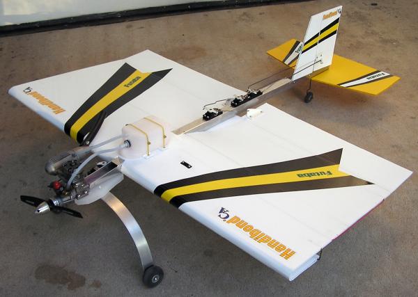
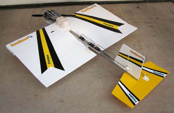
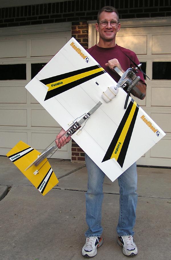
| After a summer of thrashing
the original SPA3D, I decided to make my next one a little tougher.
Thanks to all the feedback and flight reports on the forums, this
is what I came up with. The "T" in SPA3DT stands for "Tubular" but
I also like "Tank" so take your pick! To build this airplane, you must
be very familure with the original
SPA3D
plans and Instructions. All I am presenting here is a photo
essay of what I did differently on this airplane, to give you more
ideas to work with. Fuselage length, wing measurements, tail measurements
and engine mount measurements are all identical to the original SPA3D.
The square aluminum fuselage material I used is much harder to work
with than the original SPA3D's "U" channel. It is also harder to
find and more expensive, but the result is a very clean, very tough
airplane with no flex and much better high speed performance. At the
same time, this airplane retains the original SPA3D's awesome slow
flight performance, and the all up flying weight is identical to the
original at 4 pounds 8 ounces. For power I'm using a beat up TT Pro .46
and a GP 10 ounce fuel tank. I've flown this airplane with several
different prop sizes and brands, and my favorite for this engine/airplane
combination is the APC 12 x 4. Hover is at slightly more than half
throttle, with plenty of power for vertical climb outs and all the
tricks you can think of! |
|
The fuselage material is
a 36" long x 1" square x 1/16" thick section of aluminum tubing.
I found it at TSC's for $9.50 for the 36" piece. Cool, it comes in
the exact length for the airplane! Some LOWES also carry it. Since
36" of the tubing is approximately 2 1/2 ounces heavier than the
original SPA3D's "U" channel fuselage, you will notice that I have
eliminated the Coroplast profile fuselage to save weight. For the
landing gear I used a 20" long x 1" wide x 1/8" thick piece of aircraft
grade T6 aluminum. It is shaped on a sheet metal roller where I work.
It is light, very springy and VERY tough!
|
|
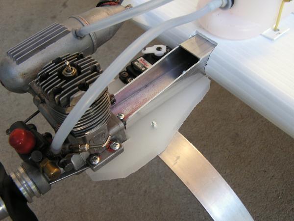
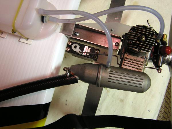
In the picture below you
will notice that I tapered the front of the aluminum tubing fuselage
for access to mount the engine mount, as well as shave off some weight.
This taper is 3" long, and goes to a wall height of 1/2" at the
front of the fuselage. I accomplished this using a hack saw, then
cleaning it up with a dremel stone, and finally removing the burrs
with a flat file. As with the original SPA3D, the fuselage is secured
to the engine mount with #6 x 3/4" self tapping screws into 1/16"
pilot holes. The landing gear and engine are also mounted to the
engine mount using these screws. I cannot stress enough that
the kitchen cutting board you use for the engine mount must say POLY
on the lable. The best brand (and the one I use exclusively!) is
"American Chef" and is available at Wal-Mart.
|
|
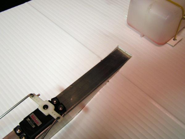
Another thing I did differently
from the original SPA3D is switch places between the throttle servo
and the landing gear mount location. Although I have never broken
a cutting board engine mount, I've read reports on the forums where
mounts had broken between the throttle servo cut-out and engine cut-out.
By switching these, there is much more "meat" behind the engine for
a tougher mount. You will also notice that I have shaved some dead
weight off of the corners of the engine mount, especially a very large
piece from the left rear. You may also notice the nice camera strap
hanging in the picture below.
|
|
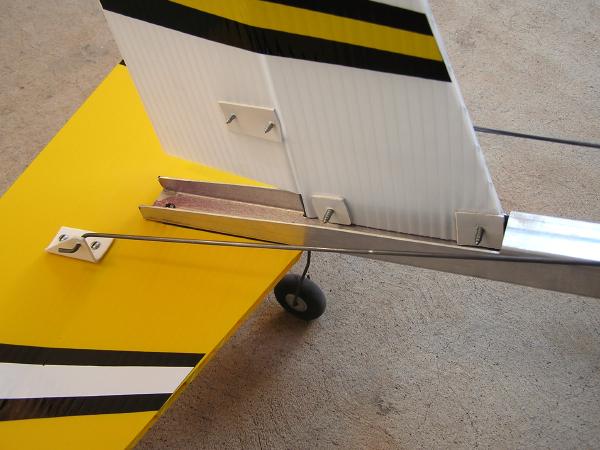
The picture below shows the
rear fuselage taper to facilitate tail mounting and shave off some
more weight. This taper is 8" long and goes to a wall height of 1/2"
at the rear of the fuselage. You will also notice that I moved the
vertical stab/rudder 2" further forward than the original SPA3D.
The ONLY reason I did this was because I think it looks cooler. Another
very helpfull hint here is to add a few drops of CA glue to the tail
mount PVC doublers before screwing them down. This will keep the
Coroplast holes from elongating and pulling out from hard dirt doinkers.
|
|
The picture below shows what
I believe is the single most important improvment to this airplane.
A poster named Coasty at
Spadworld
came up with this idea and it it brilliant! First of
all, the wing's fuselage cut-out needs to be enlarged to 1" wide
to accomidate the wider fuselage. Then note that the forward 18"
piece of 5/32" music wire spar no longer runs in the wing flute just
forward of the fuselage cut-out. It is now positioned 1" back from
the forward edge of the cut-out, and RUNS THROUGH the fuselage! To
accomplish this, I cut the wing out and positioned it on the airplane
and marked for the location of the hole. The hole is near the top
edge of the aluminum tubing. I then removed the wing and drilled
the 5/32" hole through the fuselage USING A DRILL PRESS to make
sure it was straight and square. When installing the wing on the
fuselage, I used a 1/8" piece of music wire as a "drift" to knock the
5/35" music wire spar in place, through the fuselage, centered in the
wing.
|
|
The picture below shows the
other two wing mount locations. One securing the wing trailing edge
and the other securing the forward lower wing. I used PVC doublers
and #6 x 1/2" self taping screws. I drilled the holes in the aluminum
slightly undersized, and self tapped the screws right into the aluminum.
They aren't going anywhere! Again, a couple drops of CA glue on the
doublers before tightening the screws down, will help prevent the
holes in the Coroplast from elongating on hard weed floppers. I would
also like to note that I increased the length of the rear 5/32" music
wire spar, that runs in the wing flute just in front of the ailerons,
to the full 36" wing span. You can see this clearly in some of the
overview pictures on this page. This gives the ailerons more support
and the wing less opposing flex. Make sure the rear 5/32" music wire
spar is in place before tightening down the rear wing mount screw.
I put the wing on it's side on the floor and pounded it in with a hammer.
|
|
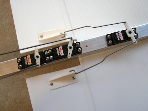
The picture below shows the
hardest part of building this airplane. The servo cut-outs in the
aluminum fuselage. Once I determined where I wanted them, I used
the servos to mark the cut-out locations. I then drilled a hole in
the corner of each cut-out. I then used a Dremel cut-off wheel to
cut between the corner holes. Using a servo for test fitting, I cleaned
up the holes with a Dremel stone until the servos fit in the cut-outs.
I then took the burrs off with a flat file. Then, using a servo as
a template, I drilled for the servo screws using a 1/16" drill bit.
Then, using servo screws, and working gently in and out with a drop
of oil, I carefully tapped each hole. This was fun because I broke
several servo screws doing this, but was able to get the broken pieces
out of the hole with small vice grips. You will notice when you go
to put your servos in, that the bottom of the servo rests on the bottom
inside of the fuselage slightly before the servo ear grommets contact
the top of the fuselage. No problem, I tightened the servo screws
down anyways, and the grommets made contact with a little flex, and the
servos are nice and tight. I did check the servos screws between every
flight on the first afternoon of flying, and they didn't losen up
at all. You will also notice that there is juuuust enough room between
the servo and the inside side wall of the fuselage for the servo
wires to run. This also made for a headache trying to get the servos
in. I ended up scotch taping the wires to the inner side of the fuselage
while installing the servos, then pulling the tape out once the
servos were in place. Even though I don't drink, by this time I
was ready for a beer...so I had a Pepsi and a cigarette instead.
You will also notice in this picture that I increased the base length
of the aileron control horns to 2 1/4" for a bigger "footprint"
and less control surface flex.
|
|
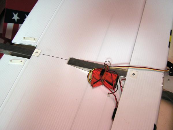
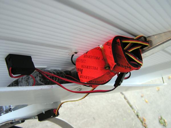
The picture below goes with
the picture above, because you cannot install the servos until you
route the wires through the fuselage. You will notice that the wires
exit the fuselage through a hole just below the forward 5/32" music
wire spar. To make the hole, I drilled two 1/4" holes next to each
other and then connected them into an oval with a dremel stone. Make
sure you smooth and deburr this hole really well so that it doesn't
cut through your servo wires. To route the wires, I held the airplane
on it's nose as I put the servos in their cut-outs. I then used a
piece of coat hanger with a small hook bent on the end to grab the
wires and pull them out of the hole. You have to hold your glutes
just right, squint a little, roll your tounge and cuss a lot, but
you can get it. This picture also shows the battery installation with
double sided foam mounting tape, as well as the switch location I used.
The Rx is simply mounted with a zip-tie to the fuselage and the antenna
routes down a flute out to the wing tip.
|
|
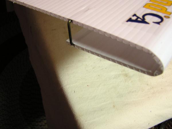
The picture below proves
that the wing's leading edge doesn't have to be perfect. Also, since
the fuselage has a larger O.D. you will need to crease 8 flutes for
the leading edge instead of 5 flutes on the original SPA3D. Make
sure that the first of the folded flutes is still at 5" from the
top edge of the Coroplast, so this means that you will be adding
the three extra flutes to be folded, to the side closest to the
top edge of the Coroplast, on the SPA3D wing layout drawing. Also
the wing leading edge fuselage hole will need to be enlarged to 1"
wide x 8 flutes long. The wing tip coat hanger clips also need to be
enlarged to 1" wide.
|
|
You may have noticed while
viewing these pictures that I am using pushrods that have a Z-bend
at both ends. I simply make them slightly longer than needed, and
then put a "zig-zag" in the middle. To adjust them, I take the servo
arm off, and make the "zig-zag" sharper or shallower using pliers.
I started doing this about a year ago when Kraut crashed an airplane
because a clevis end stripped out. Not only that, but I can buy
a bunch of music wire and not have to worry about needing anything
else to rig my plane out with. I LOVE this method, it doesn't get
any simpler, and there is nothing to break or strip out. All the
pushrods on this airplane are made from 3/32" music wire. Making
the Z-bends is TOUGH, but well worth the effort. I have been scolded
several times for running such long single wire pushrods, but this is
usually by conventional builders with very little grasp of what we
do, and with no knowledge of how tough and stiff the music wire really
is! It is PLENTY stiff and strong enough to run the control surfaces
in any normal flight you could ever put this airplane through, while
at the same time, will bow slightly in a hard tail touch or dirt
nap cartwheel...so that your servo will survive and your plane will
fly on! Do this with a conventional wood-soft metal-clevis pushrods,
and you will break, bend, or strip out something, and it could be
the end of your flying afternoon. I rigged this airplane out just
like my original SPA3D with as much throw as I could get on all the
control surfaces. The CG range on this airplane is between 6" and
7" from the leading edge (set with an empty tank), depending on
how radical you want it to fly. I currently have mine set at 6 1/4"
and like it. I hope this photo essay has given you enough information
to give you some good ideas for building your next SPA3D type airplane,
and if you have further questions, please ask them at
Spadworld
or any of the other fine Spad forums listed on the
Spad home page
.
|
|
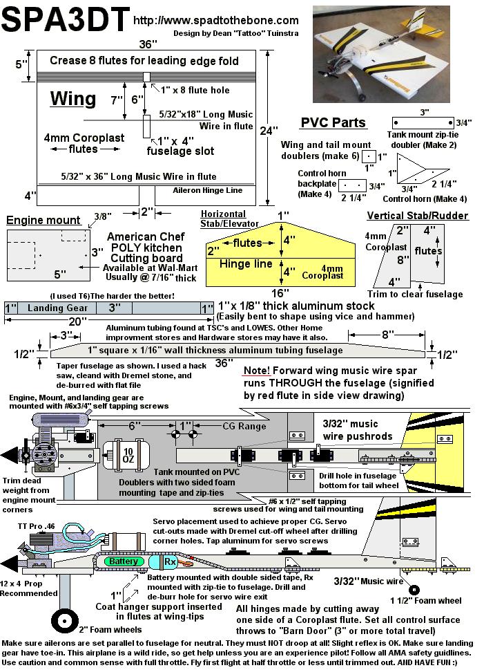
And last but not least,
below is the reference drawing for measurements. I added this drawing to
the page after doing the photo essay above, so it has all the necessary modifications
mentioned. I hope you have fun with this airplane, and don't get too mad
at me while you're making servo cut-outs and snaking your wires through the
fuselage :)
|
|
Back to the Spad Originals Index Page
|